Final Software Implementation:
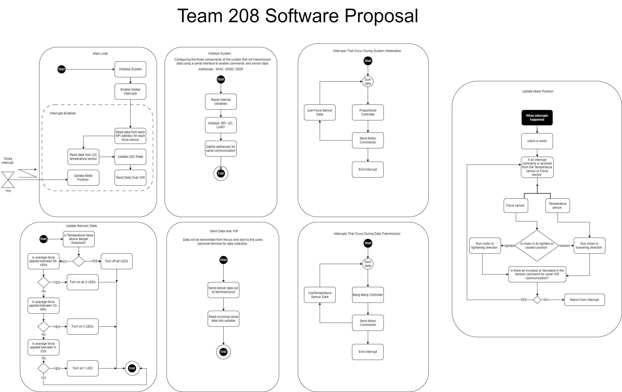
Description: For this project we decided to break up our software proposal into multiple different sections as we believed it would be easier for readers of this report to understand. Each section shows how that part will operate and what it does as well. We have the main loop showing how the overall process will happen along with the chain showing how the wifi will communicate with UART and the ESP32 device. The LED loop shows how many LEDs will turn on depending on how much force is applied to an object by a user when they are wearing the glove. Depending on how much force is applied either the green or the red LED will then turn on. The team used only one interrupt to run the update motor function every second. The indecation from either the red or green LED turning on will allow the user to know if they are applying to much pressure to a object andthis will serve as a warning preventing something from getting crsuhed or broken sastifying user needs. The product requirements called for a device that can sense two different variables. Our glove is able to sense both temperature and pressure.
Software Design Process: The team designed the software diagram to be analogous to the functions that would be used in the actual C code. This meant that the conversion from diagram to code would be easier and cleaner than EGR304. The team had some experience with C coding, but we were inexperienced with the intricacies of creating functions, this caused some problems but with adequate research and practice we overcame them.
Biggest Changes to the Software Diagram:
- The interrupt was moved. Initially the team thought about implementing the required interrupt as a timer for the motor function. It would have fired every second and updated the motor with the correct speed and direction. Instead, it was found that the interrupt was easier and more efficiently implemented on the ESP32 Rx ISP. This made it so that incoming data was handled right away.
- Mathematical control loops were rejected. Initially the team thought that using a PID controller or a bang bang controller would be effective. This proved to be time intensive and would have required more extensive knowledge of C so it was rejected. The control structure was replaced by if and else statements.
- SPI control was rejected. Due to the struggle of the team to get SPI functionality, in the last few days the team rejected the attempted use of SPI control. This was our major shortcoming in the project.
- Separate functions for the ESP32. The team initially thought one function would be good enough for bidirectional communication with the ESP32. We discovered that it is easier to split receiving and sending data into different functions. This also helped us when defining an ISP function for the Rx interrupt.
- Two functions for sensor reaction. The team initially thought that LED control and motor control should be in the same function. This was changed once it was discovered that it was easier and cleaner to separate them. This was mainly due to the large amount of work done on the motor function and no major changes to the LED function.
Version 2.0 Software Design Proposals: In the future I think the team should consider creating the software diagram and not using it as a reference. Instead, I think the team should have continued to break the diagram into pseudo code then real lines of code. This would have decreased the chance of misinterpretation of the software diagram when working separately. Function division should be changed as well. There should be two functions for ESP32 control, one for motor control, one for sensor input data handling, and one for LED control. The interrupt should also be described in more detail as well, the functionality was misinterpreted once as well. There should be no while loops that can spiral into death loops. Only for loops should be used in the individual functions with set increments and limits. Flag variables should be used whenever possible with if statements. Checking if a function should run is better than running it every time. This is similar to our motorcontol variable in the final version of the code. It checked if the motor had gotten to its run time limit before running the motor activation if statement.
MPLAB Main.C Code:
#include <stdbool.h>
#include <stdint.h>
#include <stdio.h>
#include "mcc_generated_files/mcc.h"
#include "mcc_generated_files/spi2.h"
#include "mcc_generated_files/examples/i2c1_master_example.h"

#define address 0b1001100 //hex 0x4C //hex through hole 0x48
#define tempreg 0x00

void INIT_FULL_SYSTEM(void)
{
    //system init
    SYSTEM_Initialize();

    //resource init
    I2C1_Initialize();
    EUSART1_Initialize();
    SPI2_Initialize();
    I2C1_Initialize();
    PWM6_Initialize();

    //interrupt init
    INTERRUPT_GlobalInterruptEnable();
    INTERRUPT_PeripheralInterruptEnable();
}

void Update_LED_State(uint8_t tempc, uint8_t tempmax)
{
    //check if temp value in F is above danger threshold (85)
    if (tempc >= tempmax) {
        LED_1_SetHigh();
        LED_2_SetHigh();
        LED_3_SetHigh();
        __delay_ms(100);
        LED_1_SetLow();
        LED_2_SetLow();
        LED_3_SetLow();
        __delay_ms(100);

    }
}
int Update_Motor(uint8_t tempc,uint8_t tempmax, int motorchange)
{

    if (motorchange <= 4500){
        if (tempc >= tempmax) {
            //MOTOR_CS_SetLow();
            //__delay_ms(50);

            PWM6_LoadDutyValue(1000);
            DIR_SetHigh();

           // MOTOR_CS_SetHigh();

            __delay_ms(2000);
            motorchange = motorchange+2000;
        }
    }else{
        //MOTOR_CS_SetLow();
        //__delay_ms(50);
        PWM6_LoadDutyValue(0);
        MOTOR_CS_SetHigh();
    }

    if (motorchange >= 0){
        if (tempc < tempmax) {
            //MOTOR_CS_SetLow();
            //__delay_ms(50);

            PWM6_LoadDutyValue(1000);
            DIR_SetLow();

            //MOTOR_CS_SetHigh();
            __delay_ms(1000);

            motorchange = motorchange-1000;
        }
    }
    else {
        //MOTOR_CS_SetLow();
        //__delay_ms(50);
        PWM6_LoadDutyValue(0);
        MOTOR_CS_SetHigh();
    }
    return motorchange;
}

uint8_t* read_Sensor_Values(void)
{
    uint8_t tempc = 0;
    tempc = I2C1_Read1ByteRegister(address, tempreg);
    return tempc;
}

void ESP32_Send_Sensor_Data(uint8_t tempc)
{
     printf ("TEMP = %uC\r\n", tempc);
    __delay_ms(1000);
}

void ESP32_motor_command(void){

    EUSART1_Receive_ISR();


    if (EUSART1_is_rx_ready()) {

        //LED_2_Toggle();
        unsigned char receivedByte = EUSART1_Read();
        int decimalNumber = (int)receivedByte;
        if (receivedByte == 99){
            DIR_SetHigh();
            //backward
        }
        if (receivedByte == 114){
            DIR_SetLow();
            //Forward
        }
        printf("Motor Speed changed to %d\r\n",receivedByte);

    } else {
        printf("RX PIN NOT READY\r\n COMMAND REJECTED\r\n");
    }
}


void main(void)
{
    //Init system,resources,and interrupts
    INIT_FULL_SYSTEM();

    //all variables used in main loop
    uint8_t tempc;
    uint8_t tempmax = 30;
    EUSART1_SetRxInterruptHandler(ESP32_motor_command);
    int motorchange = 0;
    DIS_SetLow();
    __delay_ms(500);
    while (1)

    {
        //read all 4 sensor values into an array of 4 length
        tempc = read_Sensor_Values();

        //Updates LEDs based on sensor values
        Update_LED_State(tempc, tempmax);

        //updates motor with sensor values

        motorchange = Update_Motor(tempc, tempmax, motorchange);

        //printf("motorspeed: %d\r\n", motorspeed);
        //sends sensor data to mqtt server
        ESP32_Send_Sensor_Data(tempc);

    }
}
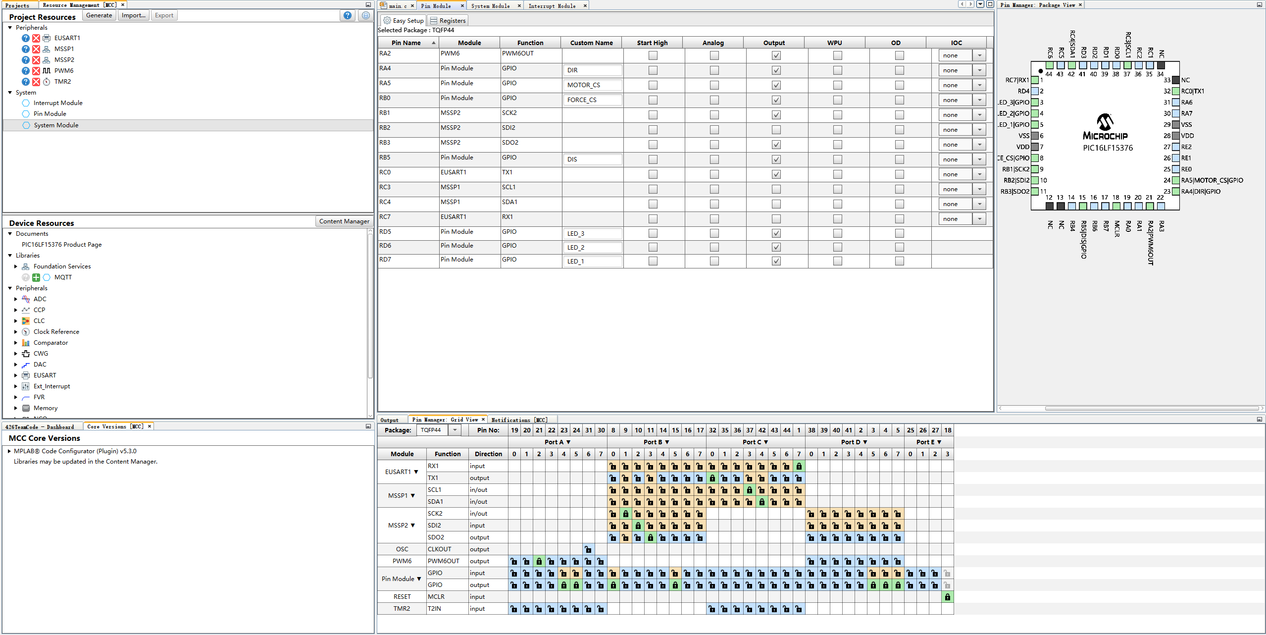
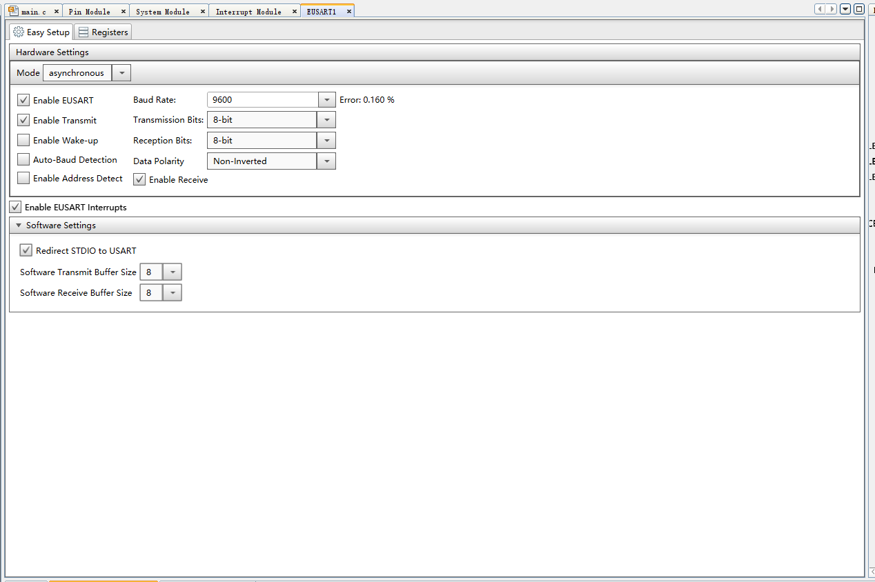
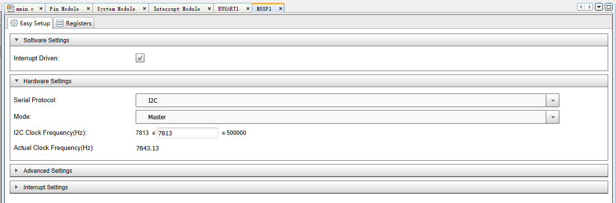
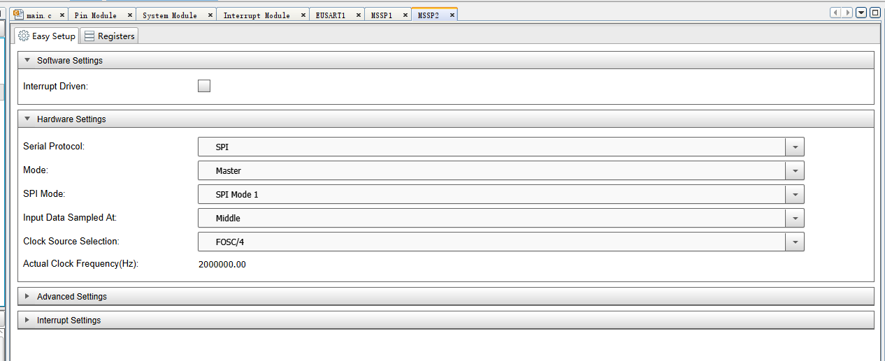
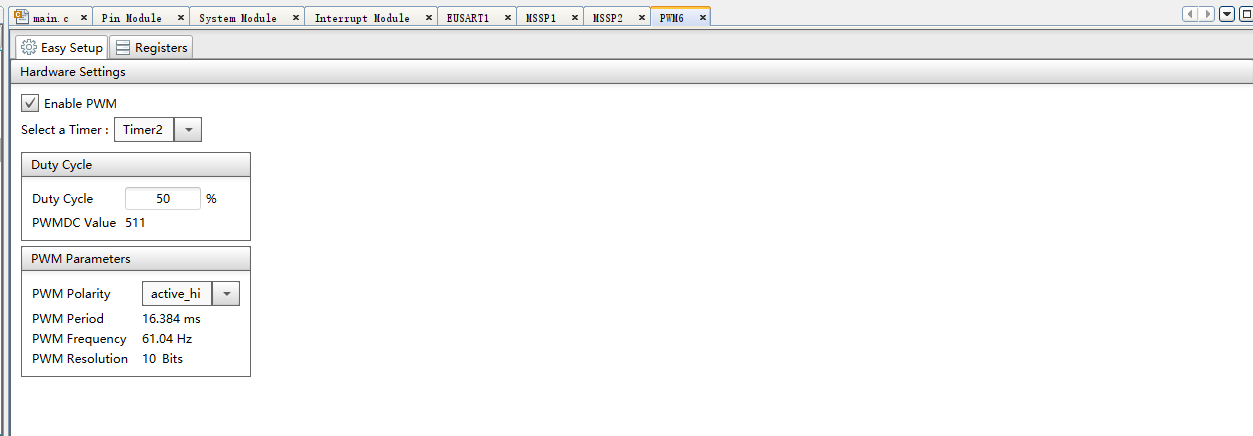
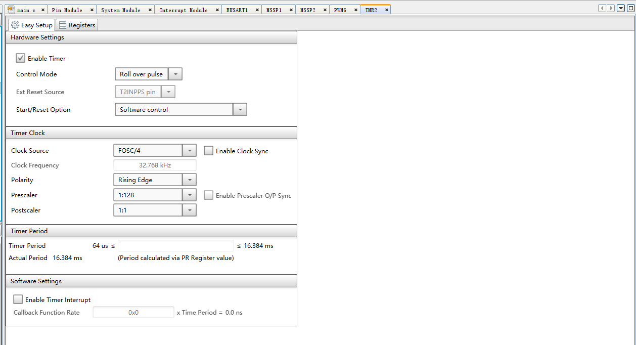
MCC configuration setting:
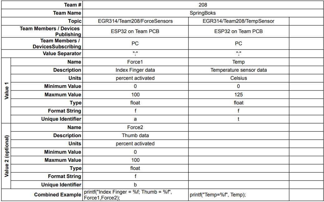
MQTT topic table setting: