Component Selection
List of Major Components:
| Part Name/Description | Unit Quantity |
|---|---|
| Temperature Sensor Digital BOM | 1 |
| 0.1 µF Ceramic Capacitor, +/-10%, X7R, 50V, 0805 package | 4 |
| 10K Ohm resistor surface mount | 4 |
| Temperature Sensor Digital | 4 |
| Barrel Jack | 2 |
| 4.7K Ohm resistor surface mount | 2 |
| Shared Test Points BOM | |
| Test Points | 6 |
| LED - Green | 2 |
| 220 Ohm resistor surface mount | 4 |
| Motor and Motor Driver BOM | |
| 0.033 µF ±10% 25V Ceramic Capacitor X7R 0805 | 4 |
| CAP ALUM 100UF 20% 25V SMD | 4 |
| 0.1 µF ±10% 50V Ceramic Capacitor X7R 1206 | 4 |
| 40V 100Ma Diode | 2 |
| Connector Header Through Hole 6 position 0.098” (2.50mm) | 2 |
| Connector Header Through Hole 12 position 0.100” (2.54mm) | 2 |
| 5V DC MOTOR | 1 |
| Full Half-Bridge Drivers | 2 |
| Microcontroller and Voltage Regulator BOM | |
| LM2575 Voltage Regulator | 6 |
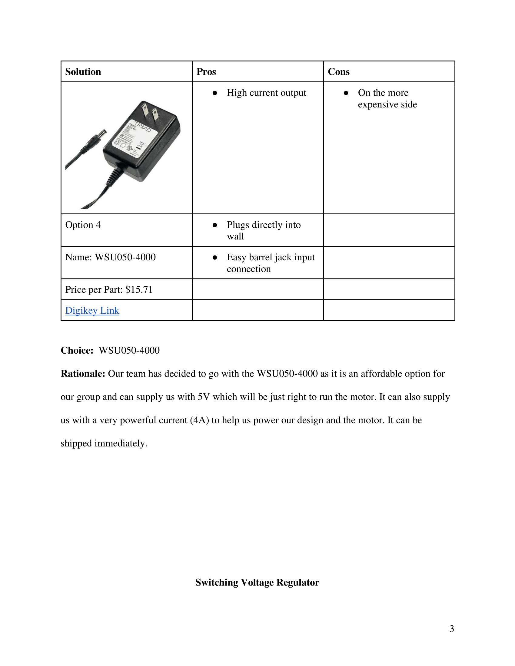
| WSU050-4000 AC/DC Convertor | 1 |
| PIC16F18876-I/PT Microcontroller | 3 |
| Force Sensor | |
| IC ADC 24 BIT SIGMA-DELTA 20 TSSOP | 2 |
| Op-Amp for Force Sensor | 2 |
| Sensors RoHS | 2 |
| 1K Ohm resistor surface mount | 2 |
Description:
- The bill of materials contains all the parts each section of the nerve damage therapy glove will be utilizing. All parts meet the requirements and unless specified otherwise are surface mounted. Everything from the voltage regulators to the OP-AMP and even our resistors and capacitors are surface-mounted. The only parts that aren’t surface mounted are the barrel jack, motor, microcontroller, and wall plug to supply power to the device. A variety of communication methods are utilized such as SPI, UART, and I2C. Our wall power supply supplies voltage at a measurement of 5V and 1A to a switching voltage regulator. From the switching voltage regulator the power drops down and comes out to 3.3 V. Our force sensors are resistive which utilize an ADC device to convert their analog signals to SPI so it can be read by the microcontroller. The ESP32 utilizes UART to communicate all this data over wifi to a digital storage space such as someone’s personal device or the medical records system at a doctor’s office.
Power Budget Table:
| Power Budget | |||||||
|---|---|---|---|---|---|---|---|
| Team Number: | 208 | ||||||
| Project Name: | Nerve Damage Thearpy Glove | ||||||
| Team Member Names: | Miles Wilson, Kyle Selasky, Mingqi Yu, Felicia Szleszinski | ||||||
| Version: | 1 | ||||||
| A. List ALL major components (active devices, integrated circuits, etc.) except for power sources, voltage regulators, resistors, capacitors, or passive elements | |||||||
| All Major Components | Component Name | Part Number | “Supply | ||||
| Voltage | |||||||
| Range” | # | “Absolute | |||||
| Maximum | |||||||
| Current (mA)” | “Total | ||||||
| Current | |||||||
| (mA)” | Unit | ||||||
| Force Sensor | GHF-10 | +3.3-5V | 3 | 100 | 300 | mA | |
| Force ADC SPI Chip | MCP3562RT-E/ST | 1.8-3.6V | 1 | 100 | 100 | mA | |
| Temperature Sensor | HIH6030-021-00 | +2.7-5.5V | 1 | 650 | 650 | mA | |
| Motor | JSX5300-370 | +5V to -5V | 1 | 240 | 240 | mA | |
| Motor Driver | IFX9201SGAUMA1 | 0-50V | 1 | 500 | 500 | mA | |
| ESP32 | ESP32WROOM32 | 3-3.6V | 1 | 150 | 150 | mA | |
| Switching Regulator | LM2575 | +2.3-6V | 1 | 7 | 0.08 | mA | |
| “B. Assign each major component above to ONE power rail below. Try to minimize the number of different power rails in the design. | |||||||
| Add additional power rails or change the power rail voltages if needed.” | |||||||
| +3.3V Power Rail | Component Name | Part Number | “Supply | ||||
| Voltage | |||||||
| Range” | # | “Absolute | |||||
| Maximum | |||||||
| Current (mA)” | “Total | ||||||
| Current | |||||||
| (mA)” | Unit | ||||||
| Force Sensor | GHF-10 | +3.3-5V | 3 | 100 | 300 | mA | |
| Temperature Sensor | HIH6030-021-00 | +2.7-5.5V | 1 | 650 | 650 | mA | |
| Force ADC SPI Chip | MCP3562RT-E/ST | 1.8-3.6V | 1 | 100 | 100 | mA | |
| ESP32 | ESP32WROOM32 | 3-3.6V | 1 | 150 | 150 | mA | |
| 0 | mA | ||||||
| Subtotal | 1200 | mA | |||||
| Safety Margin | 25% | ||||||
| Total Current Required on +3.3V Rail | 1500 | mA | |||||
| c1. Regulator or Source Choice | +3.3V Switching Regulator | LM2575 | 4.75V-40V | 3.3 | 1000 | 3300 | mA |
| Total Remaining Current Available on +3.3V Rail | 1800 | mA | |||||
| C. For each power rail above, select a specific voltage regulator using the same process as for major component selection. Confirm that the Total Remaining Current Available on each rail above is not negative. | |||||||
| D. Select a specific external power source (wall supply or battery) for your system, and confirm that it can supply all of the regulators for all of the power rails simultaneously. If you need multiple power sources, list each separately below and indicate which regulators will be connected to each supply. Confirm that the Total Remaining Current Available on each power source below is not negative. | |||||||
| External Power Source 1 | Component Name | Part Number | “Supply | ||||
| Voltage | |||||||
| Range” | Output Voltage | “Absolute | |||||
| Maximum | |||||||
| Current (mA)” | “Total | ||||||
| Current | |||||||
| (mA)” | Unit | ||||||
| Power Source 1 Selection | Plug-in Wall Supply | WSU050-4000 | 90 ~ 264 VAC | 5V | 4000 | 4000 | mA |
| Power Rails Connected to External Power Source 1 | |||||||
| +3.3V Switching Regulator | LM2575 | 4.75V-40V | 3.3 | 1000 | 3300 | mA | |
| Motor Driver | IFX9201SGAUMA1 | 5V-50V | 5V | 500 | 500 | ||
| Total Remaining Current Available on External Power Source 1 | 200 | mA | |||||
| E. Calculate Battery Life (if applicable). For each battery, also check the worst-case lifetime of the battery by indicating the capacity in mAh. | |||||||
| Component Name | Part Number | “Supply | |||||
| Voltage | |||||||
| Range” | “Capacity | ||||||
| (mAh)” | “Required | ||||||
| By | |||||||
| Regulators” | |||||||
| N/A | N/A | N/A | N/A | N/A | N/A | ||
| Battery Life | N/A | hours | |||||
| Notes | |||||||
| External Supply Voltage should be determined by the dropout voltage for highest-voltage regulator (e.g., +14V for a +12V regulator). | |||||||
| If you have multiple units in your design (e.g., a base unit and remote unit) then you need a separate power budget for each unit |