Block Diagram
Description:
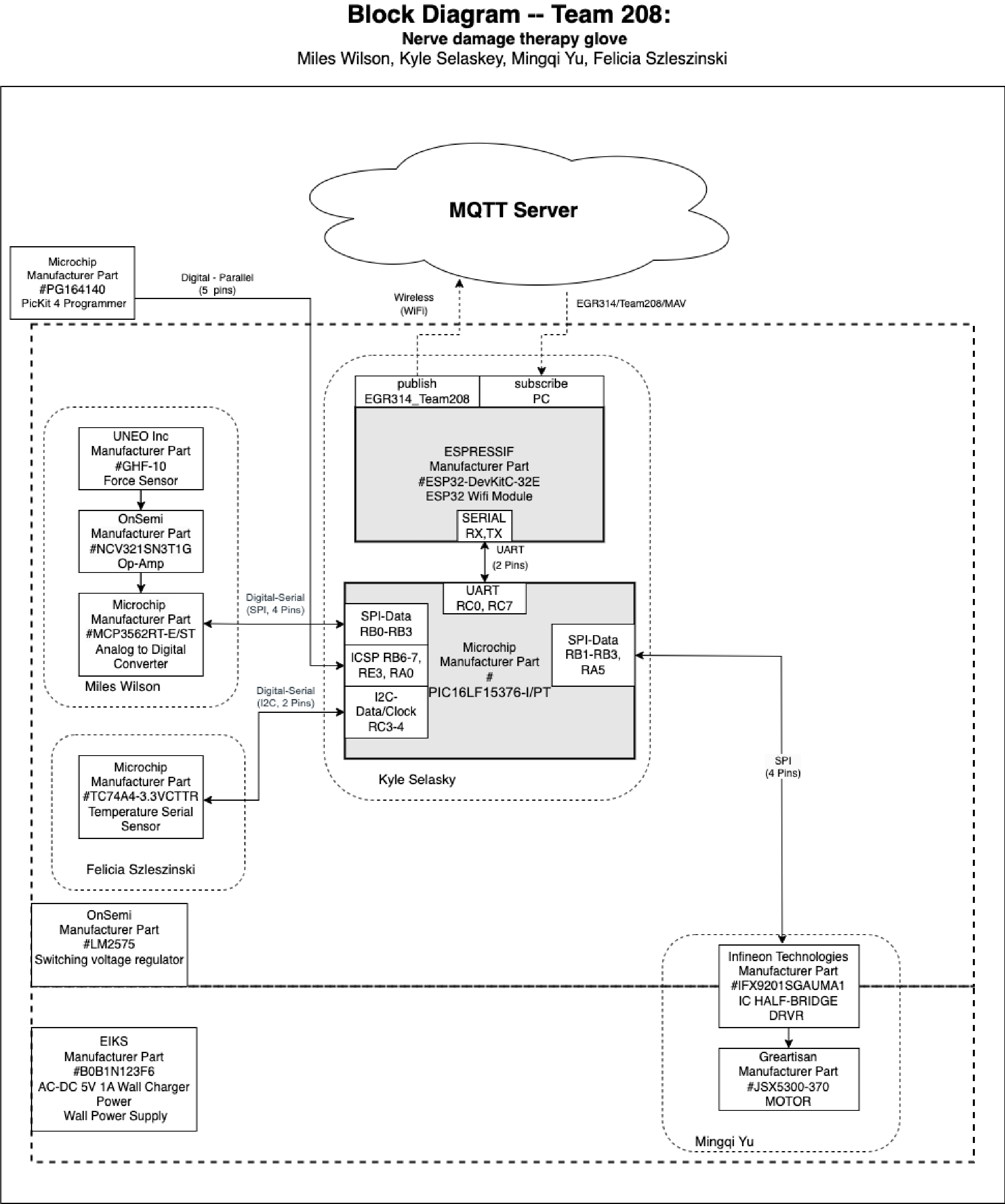
To provide power for our pressure glove for nerve damage, we will be using a 5V, 1A wall outlet to operate the device. The power will flow into a voltage regulator, which will output 3.3V and proceed to the microcontroller. The microcontroller will communicate with all our sensors and receive data. When the user wears the glove and grips something, the thin-film pressure sensors will send that information back to the microcontroller via an ADC, which will convert it into an SPI signal. The ESP32 Wi-Fi module will utilize UART to upload the data to the server at a medical facility or to a phone.
When revising our block diagram, we received feedback aimed at enhancing our design. In order to confirm that our project requirements were being met, we ensured that the bidirectional communication blocks had bidirectional arrows, consolidated the SPI and I2C blocks into one block per subsystem, and indicated that the 5V power was separate from the main subsystems.
By incorporating these changes, we were able to provide a more precise depiction of how our design would operate and be controlled, ensuring that it met our project requirements.